About the Earth's ionosphere
Ionosphere
The ionosphere is the ionized part of the Earth's upper atmosphere, located at altitudes from about 50 to 1000 km. Its main feature is a significant content of free electrons and ions.
Major factors influencing the processes in the ionosphere:
- ultraviolet and X-ray radiation ofthe Sun,
- cosmic rays passing through the Earth's atmosphere
- the Earth's magnetic field
Ionization occurs mainly due to the solar activity, therefore there is a strong dependence of the ionospheric properties on position and time:
- depending on longitude, latitude and altitude above the Earth's surface,
- during the day,
- depending on the time of a year,
- depending on the solar activity cycle phase
The state of ionosphere is described by several parameters: the electron content in the ionosphere, ionic composition, ionic and electron temperatures, particles velocity, etc. At the same time, from a practical point of view, for global navigation satellite systems (GNSS), the key parameter is the electron content in the ionosphere, since it directly affects the radio waves propagation and causes an ionospheric delay in pseudorange measurements.
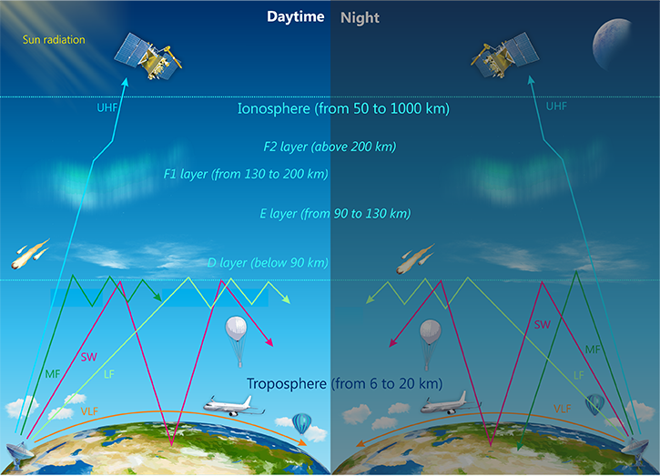
Depending on the height and electron content distribution, the ionosphere is conventionally divided into layers: D (below 90 km), E (from 90 to 130 km), F1 (from 130 to 200 km) and F2 (above 200 km). The maximum ion and electron concentration is located in F2 layer at 250 – 450 km height.

Fig. 1. The ionospheric influence on radio waves
THE IONOSPHERIC INFLUENCE ON RADIO WAVES AND GNSS SIGNALS PROPAGATION
The ionosphere significantly affects the radio waves propagation, in particular, GNSS signals. The influence on the radio waves propagation is mainly exerted by the wave frequency and free electrons in the ionosphere, which make the ionosphere a dispersive medium for radio waves, where the propagation speed depends on the wavelength. For this reason, propagation delay and radio waves’ trajectory refraction occur in the ionosphere, and even ionospheric reflection for certain wavelengths. Table 1 lists ways of radio wave interaction with the ionosphere, depending on the wavelength:
The ways of radiowave interaction with the ionosphere
| Bands | Wavelength | Frequency | The way of interaction with the ionosphere |
|---|---|---|---|
| Very low frequency (VLF) | 100 km - 10 km | 3 - 30 kHz | Absorbed by the ionosphere, propagated by the envelope surface wave along the Earth |
| Low frequency (LF) | 10 km - 1000 m | 30 - 300 kHz | |
| Medium frequency (MF) | 1000 m - 100 m | 300 kHz - 3 MHz | Absorbed by the ionosphere during the day, reflected at night |
| High frequency (HF) | 100 m - 10 m | 3 - 30 MHz |
Reflected by the ionosphere. Radio |
|
Ultrashort waves. Wavelengths range from millimeter to meter. In particular, GNSS signals have wavelengths within the meter (ultra-high frequency, UHF) GNSS signals |
10 m – 0.1 mm | 30 MHz - 3000 GHz |
Propagate within the line of sight. Pass through the ionosphere |
GNSS signals belong to the ultrashort wavesand propagate within the line of sight. Rare cases of GNSS signal loss in ground receivers have been observed during ionospheric storms in equatorial latitudes. It is also possible to mention another exceptional example of GNSS signals loss by a receiver installed on the descent vehicle, that enters the Earth's atmosphere at high velocity; a visible plasma shield (ionized gas) forms around it due to the shock wave, blocks radio signals and deprives the vehicle of the radio communication for a few minutes. Such examples are a rare exception, and as a rule, the ionospheric delay is included in the GNSS pseudorange measurements as a correction that is directly proportional to the electron content along the entire signal path and is inversely proportional to the square of the signal frequency in the first approximation.
From the point of view of the ionospheric influence on the positioning accuracy, navigation receivers are divided into two types: single-frequency and dual-frequency (multi-frequency in general). While using dual-frequency receivers, mainly referred to as geodesic class equipment, it is possible to avoid the influence of ionospheric delay using the so-called ionosphere-free combination of pseudorange measurements at first and second frequencies. However, for single-frequency receivers, which form the basis of the mass market, the problem of ionospheric influence remains open; in their case ionospheric delays cause a positioning error from a few meters to tens of meters. To solve this problem, it is necessary to build ionospheric models of the total electron content (TEC). Exactly for this purpose, ionospheric model parameters are included in broadcast messages of GNSS and augmentation systems.
IONOSPHERIC MODELS
Existing ionospheric models as applied for GNSS can be conventionally divided into two groups:
- complex physical ionospheric models,
- single-layer ionospheric TEC models (and three-layer).
The most detailed and qualitative ionospheric models are complex physical models of the first conventional group, which are based on physical laws of magnetic hydrodynamics and kinetic equations. Such models describe physical processes in the ionosphere, evaluate a variety of indicators and their spatial distribution. In addition to GNSS measurements, data sources for physical ionospheric models are data from a global ionosondes network, powerful incoherent scattering radars, satellite probes, individual measurements from various space vehicles.
However, to determine the ionospheric delays of navigation signals, it is necessary to know only the value of the total electronic content along the signal propagation path, there is no need to determine other physical ionospheric parameters. Therefore, in fact, single-layer ionospheric models of the second conditional group are used for GNSS: local, regional and global ionospheric maps (GIM) of the total electron content as well as simplified ionospheric models in broadcast messages of GNSS and augmentation systems. The reverse is also true: the measurements of a distributed network of GNSS stations are the source of the data for constructing ionospheric TEC maps.
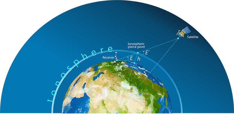
Single-layer ionospheric models are based on the assumption that all free electrons of the ionosphere are located in an infinitely thin layer at a certain height above the Earth's surface. The layer’s height is selected from 350 to 450 km. Thus, the ionospheric delay in a navigation signal depends only on the wave frequency, the elevation angle and the value of vertical total electron content (VTEC) at the ionospheric pierce point (IPP) of the model layer. The total electron content (TEC) is defined as the total number of electrons along a tube with a cross-section of one square meter and is expressed in special TEC units: 1 TECu = 1016 electrons / m2 ≈ 0.16 m for the navigation signal L1.

Fig. 2. Single-layer ionospheric model
LOCAL AND GLOBAL IONOSPHERIC MAPS OF TOTAL ELECTRON CONTENT
In the Information and Analysis Center for Positioning, Navigation and Timing (IAC PNT), as in other centers of the International GNSS Service (IGS), local and global ionospheric TEC maps are generated daily on the basis of open publicly available measurements of the globally distributed GNSS measurement station network. Simultaneously with ionospheric maps parameters, the differential code biases (DCB) of GNSS measurement stations and satellites are estimated.
To calculate local ionospheric map parameters, measurements of one GNSS station at a daily interval are sufficient, the map is constructed for an area with the radius of about 500-750 km around the utilized station. This method is mainly used for calibration of the station and satellites (through DCB estimation) as an intermediate step of calculations.
Global ionospheric maps construction using GNSS measurements is in great demand for space weather research and Earth remote sensing. The basis for global ionospheric TEC maps construction is the worldwide publicly accessible GNSS stations network deployed by the IGS and operating since 1994. IAC PNT uses open measurements of about 300 IGS stations to estimate the global ionospheric TEC maps parameters on a daily basis. The spherical harmonic (SH) expansion is used as a spatial VTEC distribution model (13 different spherical harmonic coefficients sets on a daily interval). The ionospheric maps are stored and transmitted with IONEX standard, which is a grid of VTEC values in TECu with usual spatial resolution of 2.5 degrees in latitude, 5 degrees in longitude and with 1 hour or 2 hours time resolution. Totally, it is 5183*25 or 5183*13 VTEC values for 1-hour or 2-hour daily IONEX files, respectively.
SIMPLIFIED IONOSPHERIC MODELS BROADCASTED BY GNSS
As mentioned earlier, simplified ionospheric models are broadcast by GNSS and augmentations to improve the positioning accuracy of single-frequency receivers:
- global Klobuchar K8 ionospheric model broadcast by GPS: 8 parameters every day
- global three-dimensional ionospheric NeQuick model broadcast by GALILEO: 3 parameters every day
- regional improved Klobuchar BDS_K8 ionospheric model broadcast by BeiDou-2 satellites: 8 parameters each 2 hours
- global spherical harmonic function ionospheric BDGIM model broadcast by BeiDou-3 satellites: 9 parameters each 2 hours
- global adaptive ionospheric model broadcast by GLONASS-K satellites: 3 parameters every day


 Принципы навигации
 Ионосфера
 Испытания НАП, оценка условий спутниковой навигации
 Стандарт эксплуатационных характеристик открытого сервиса