Ionosphere modeling methods
MEASUREMENTS MODELLING
Satellite navigation is based on the principle of using pseudorange measurements between navigation satellites and an autonomous receiver. The measured range differs from the true one by different delays and clock offsets, therefore it is called pseudorange. The presented model of open GNSS measurements differs from the generally accepted one by the separate division of systematic code biases into receiver and satellite biases, while systematic biases for each receiver are generally different for each satellite. This is especially important for GLONASS, because it allows to take into account the frequency division multiple access (FDMA) peculiarities and calibrate GLONASS receivers more accurately.
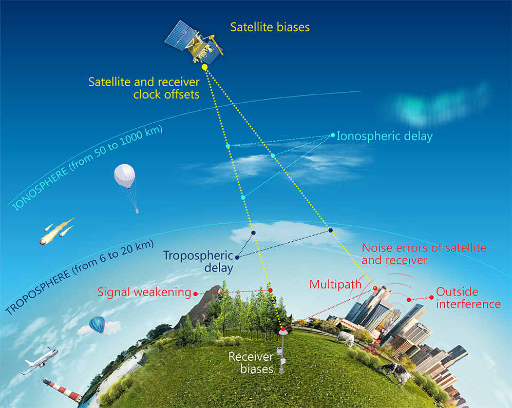
Fig. 1. Components of GNSS pseudorange measurements
The pseudorange measurements of open GNSS C/A code signals for frequencies L1 and L2 (C1C and C2C in RINEX-3 notation [1]) can be modelled by the following equations:
\[ P_{GS,C1}^{SC} = \overline{P_{GS}^{SC}} + I_{GS,1}^{SC} + b_{GS(SC),C1} + b_{C1}^{SC} + \varepsilon_{GS,C1}^{SC} \]
\[ P_{GS,C2}^{SC} = \overline{P_{GS}^{SC}} + I_{GS,2}^{SC} + b_{GS(SC),C2} + b_{C2}^{SC} + \varepsilon_{GS,C2}^{SC} \]
where
\(\overline{P_{GS}^{SC}} = \overline{\rho_{GS}^{SC}} + T_{GS}^{SC} + c(dt_{GS} - dt^{SC}) \) - pseudorange observation with tropospheric delay, satellite and receiver clock offsets,
\(\overline{\rho_{GS}^{SC}}\) - geometric true range,
\(b_{GS(SC),C1} , b_{GS(SC),C2}\) - receiver biases for C1 and C2, which depend on the satellite in general case,
\(b_{C1}^{SC} , b_{C2}^{SC}\) - satellite biases for C1 and C2,
\(\varepsilon_{GS,C1}^{SC} , \varepsilon_{GS,C2}^{SC}\) - code noise errors С1С, С2С of satellite and receiver.
Ionospheric maps in this description mean TEC (Total Electron Content) maps in the ionosphere, since only free electrons in the ionosphere affect the radio signal delay.
Ionospheric delay depends on frequency and slant total electron content (STEC) along the entire signal path:
\[ I = \frac{40.31 m^3 s^{-2}}{f^2} \cdot \int N_e d l = \frac{40.31 m^3 s^{-2}}{f^2} \cdot STEC \]
To calculate the ionospheric parameters and the differential code biases (DCB), the so-called geometry-free combination of code measurements at two frequencies is used:
\[ P_{GS,C1-C2}^{SC,GF} = P_{GS,C1}^{SC} - P_{GS,C2}^{SC} = 40.31(\frac{1}{f_1^2} - \frac{1}{f_2^2}) \cdot STEC + DCB_{GS,C1-C2}^{SC} + \varepsilon_{GS,C1-C2}^{SC,GF} \]
The total inter-frequency DCB is equal to the sum of the satellite and receiver DCBs and is defined as follows:
\[ DCB_{GS,C1-C2}^{SC} = DCB_{GS(SC),C1-C2} + DCB_{C1-C2}^{SC} = ( b_{GS(SC),C1} - b_{GS(SC),C2} ) + ( b_{C1}^{SC} - b_{C2}^{SC} ) \]
SINGLE-LAYER IONOSPHERIC MODEL
In the case of a single-layer model, the ionosphere is considered as a thin shell of constant altitude \(h\). Slant Total Electron Content \(STEC\) is estimated by the product of the Vertical Total Electronic Content \(VTEC\) and mapping function \(m(E)\), which depends on the elevation angle \(E\), the ionospheric shell altitude \(h\) = 450 km and the Earth’s radius \(R_\bigoplus\):
\[ STEC = VTEC \cdot m(E) = VTEC \cdot \frac{1}{sin(E')} \]
\[ cos(E') = \frac{R_\bigoplus}{R_\bigoplus + h} \cdot cos(E) \]
where \(E’\) – is the elevation angle at the ionospheric pierce point (IPP).
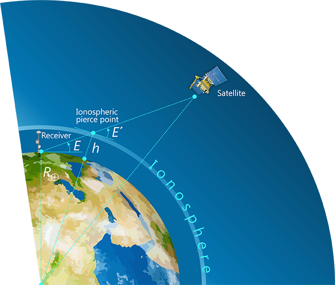
Fig. 2. Single-layer ionospheric model
According to the IGS terminology inter-frequency delays are called differential code biases (DCB), interface control documents (ICD) of foreign GNSS refer to it as GD (Group Delay), ICD GLONASS define it as the time difference between navigation radio frequence (RF) signal transmitted in L2 sub-band and navigation RF signal transmitted in L1 sub-band. Since the ionospheric delay is inversely proportional to the square of the frequency, ionospheric value is required to determine DCB. It is assumed that the difference between measurements in the L1 and L2 sub-bands is caused only by the ionosphere, DCB delays, code noise and multipath. The total contribution of noise errors and multipath for a modern geodetic-class GNSS receivers, as a rule, does not exceed 1 m even at relatively low elevation angles from 10 to 20 degrees, i.e. these errors decrease many times with multiple measurements.
Strict division of the total satellite-plus-receiver DCB observed by each station into satellite and receiver DCB components is impossible. DCB division is based on the assumption that the sum of all satellite inter-frequency DCBs is equal to zero, as well as the use of some standard, which can be an "average receiver representing the network" or several selected calibrated receivers [4]. Differential code biases are estimated in two stages:
- At the first stage, the total satellite-plus-receiver biases \(DCB_{GS,C1-C2}^{SC}\) based on the data of the globally distributed receivers network is calculated.
- At the second stage, the total DCBs are divided and differential code biases are separately calculated for satellite \(DCB_{C1-C2}^{SC}\) and receiver \(DCB_{GS.C1-C2}\)
Further, three different methods [5] are considered for modeling the total electron content TEC in the ionosphere and estimating total DCB:
- Differential code biases calculation using existing ionospheric maps
- Local ionospheric modeling and differential code biases calculation
- Global Ionospheric maps modeling and differential code biases calculation
1. DIFFERENTIAL CODE BIASES CALCULATION USING EXISTING IONOSPHERIC MAPS
The first way to estimate the total satellite-plus-receiver differential code biases \(DCB_{GS,C1-C2}^{SC}\) relatively simple and used when the ionospheric delay is known in advance [6].
For example, it is possible to use existing global Ionospheric maps (GIM), which are published in IONEX format [2] by analysis centers of the IGS [13, 14]. In addition, since 2021, the daily global ionospheric maps of TEC by IAC PNT are publicly available [11].
To determine the total differential code biases, it is enough to process one pair of receiver-satellite measurements at a daily interval; the DCB is calculated as the arithmetic average of all geometry-free measurements combinations:
\[ DCB_{GS,C1-C2}^{SC} = \frac{1}{n} \displaystyle\sum_{i=1}^{n} (P_{GS,C1-C2}^{SC,GF} - I_{GS}^{SC,GF}) \]
where the equivalent ionospheric delay for a geometric-free combination is determined by the previously described principle:
\[ I_{GS}^{SC,GF} = 40.31 m^3 s^{-2} \cdot (\frac{1}{(f_1^{SC})^2} - \frac{1}{(f_2^{SC})^2}) \cdot m(E) \cdot VTEC \]
For example, Fig. 3 shows the receiver position; the one sub-satellite trace in two visibility zones on a daily interval is marked in red, and the corresponding ionospheric pierce points are marked in blue:
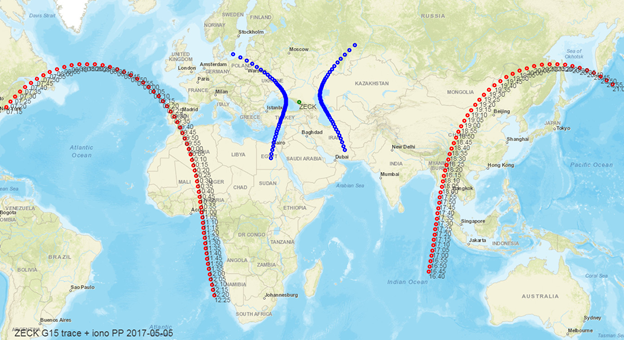
Fig.3. Sub-satellite traces and corresponding ionospheric pierce points for one receiver
Fig. 4 shows the calculation process. The known ionospheric delay (blue) is subtracted from the geometry-free measurements combination (red), the resulting difference is averaged (green). Thus, the desired differential code bias is calculated.
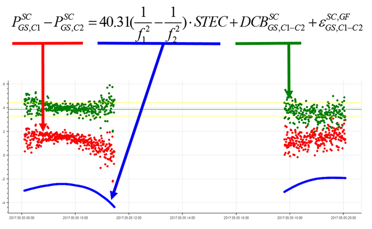
Fig.4. Geometry-free combination (red), ionospheric delay (blue), total differential code bias (green)
2. LOCAL IONOSPHERIC MODELING AND DIFFERENTIAL CODE BIASES CALCULATION
The second method for determining the total satellite-plus-receiver DCB is to estimate differential code biases \(DCB_{GS,C1-C2}^{SC}\) and local ionosphere parameters simultaneously. The calculation is performed for one receiver and all observed satellites using the least squares (LSQ) method. The advantage of this method is its sustainability and better accuracy. The local ionosphere modeling method using two-dimensional polynomial was introduced in 1999 [7]. Then the method was improved: a finite Fourier series expansion was added to the polynomial [8, 9].
Thus the total electronic content in the receiver local area is modeled depending on the geographical latitude \(\varphi\) and the sun-fixed longitude \(t\) at the ionosphere pierce point:
\[ VTEC(\varphi,t) = \displaystyle\sum_{n=0}^{n_{max}} \displaystyle\sum_{m=0}^{m_{max}} \{ E_{nm} (\varphi - \varphi_0)^n \cdot t^m \} + \displaystyle\sum_{k=0}^{k_{max}} \{ C_k cos(k \cdot t) + S_k sin(k \cdot t) \} \]
where \(\varphi\) – is geographic latitude of the ionosphere pierce point, \(\varphi_0\) – is geographic latitude of the station, \( t = \lambda - \lambda_{SUN} \) - is sun-fixed geographic longitude, it is denoted as local time in time units, \(E_{nm}\) – are polynomial coefficients, \(C_k\) и \(S_k\) – are coefficients of finite Fourier series to be estimated.
The rank deficiency is eliminated by the degree of the polynomial \( ( m_{max}, n_{max}=4 ) \), maximum degree of finite Fourier series \( (k_{max}=4 ) \), as well as by estimating the parameters for one receiver and all observable satellites (all GNSS). The ionospheric pierce points and the approximate local ionospheric area for the estimation of model parameters at the daily interval are shown in Fig. 5.
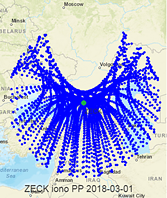
Fig.5. Ionospheric pierce points for one receiver on a daily interval
After estimating the local ionospheric model parameters and the total satellite-plus-receiver DCBs, total DCBs can be divided into the satellite and receiver differential code biases [8, 9]. To solve this problem, a certain standard is needed, that can be calibrated receivers or an "average receiver" representing the network. The resulting DCBs are stored in SINEX_BIAS format [3] files, which are published by IGS Centers [15].
At IAC PNT, the calculation of the local ionospheric parameters and the division of differential code biases have been conducted since 2017, the final DCBs in the SINEX_BIAS format are published on a daily basis [12]. The DCB estimation with regard to the GLONASS frequency division multiple access (FDMA) dependence, has been implemented using both the methods of an "average receiver" representing the network and a calibrated receiver [4].
3. GLOBAL IONOSPHERIC MAPS MODELING AND DIFFERENTIAL CODE BIASES CALCULATION
The global ionospheric TEC maps (GIM) modeling is similar to the local ionospheric mapping using one receiver observations, but in this case a globally distributed receivers network is used for the estimation. On a daily basis, DCBs for all satellite-receiver pairs and the global vertical TEC distribution are estimated simultaneously using the spherical harmonic (SH) expansion depending on latitude and solar-fixed longitude:
\[ VTEC(\varphi,t) = \displaystyle\sum_{n=0}^{n_{max}} \displaystyle\sum_{m=0}^{n} P_{nm} sin \varphi \{ C_{nm} cos (mt) + S_{nm} sin(mt) \} \]
where \(\varphi\) is the latitude of an ionospheric pierce point, \( t = \lambda - \lambda_{SUN} \) s sun-fixed geographic longitude, \(P_{nm}\) – are Legendre polynomials, \(С_{nm}\) and \(S_{nm}\) are SH expansion coefficients to be estimated. Both geographical and geomagnetic coordinates can be used in the model.
The global ionospheric maps modelling method was published in 1999 [7]. At first, only one set of SH expansion coefficients and DCBs for one daily interval were estimated. Then the method was improved [10], 25 or 13 sets of SH expansion coefficients for 1-hour or 2-hour calculation steps were calculated. Consecutive sets of coefficients can be related using some condition, for example, a Piecewise Linear (PWL) interpolation can be used:
\[ X(t) = (1 - \Delta_i(t))X(T_i) + \Delta_i(t) X(T_{i+1}), i = 1 \dots 25 \]
where \(X(t)\) is the SH expansion coefficient at arbitrary time \(t, X(T_i)\) and \(X(T_{i+1})\) are SH coefficients to be estimated, \( \Delta_i(t) = \frac{t - T_i}{T_{i+1} - T_i}\) is the weight of time \(t\) between the session times \(T_i\) и \(T_{i+1}\).
When constructing global Ionospheric maps, it is difficult to estimate the parameters in geographical areas where there are no GNSS observations, in particular, over the oceans. Since the arguments are latitude and solar-fixed longitude, time extrapolation with a low weight to empty spatial zones is used as a solution to this problem. In other words, the assumption is used that at a particular geographic point the ionosphere parameters correspond to the ionosphere parameters 15 degrees east, but 1 hour ago.
Global Ionospheric maps are stored in the IONEX format [2]. IGS Centers openly publish their IONEX files [13, 14].
At IAC PNT open measurements of about 300 IGS stations are used to estimate the global ionospheric TEC maps, GLONASS and GPS observations are used. The results are published in IONEX format on a daily basis since 2021 [11]. The spatial resolution is 2.5 degrees in latitude, 5 degrees in longitude, the time step is 2 hours.
REFERENCES
[1] RINEX.The Receiver Independent Exchange Format Version 3.05. International GNSS Service
[2] IONEX: The IONosphere Map EXchange Format Version 1.1. Stefan Schaer, Werner Gurtner. Astronomical Institute, University of Berne, Switzerland
[3] SINEX BIAS — Solution (Software/technique) INdependent EXchange Format for GNSS Biases. Version 1.00. Stefan Schaer, swisstopo/AIUB
[4] V.V.Mitrikas, I.O.Skakun, A.A.Arzhannikov, V.N.Fedotov / Application of a calibrated navigation receiver for estimating measurement error via GLONASS space segment (SISRE) // «Al’manac of Modern Metrology». 2021, № 2 (26), p. 79–103
[5] A.A.Arzhannikov, V. D. Glotov, V.V.Mitrikas / Determination of differential code biases and ionosphere maps using GNSS // The IX All-Russian Conference "Fundamental and applied scientific research in positioning, navigation and timing" PNT-2021. September 13-17, 2021 [https://iaaras.ru/meetings/kvno2021/abstracts/arjannikov/]
[6] Montenbruck, O.; Hauschild, A.; Steigenberger, P. Differential code bias estimation using multi-GNSS observations and global ionosphere maps. Navigation 2014, 61, 191–201 [https://doi.org/10.1002/navi.64]
[7] Schaer, S. Mapping and Predicting the Earth’s Ionosphere Using the Global Positioning System; Astronomical Institute, University of Berne: Berne, Switzerland, 1999.
[8] Wang, N.; Yuan, Y.; Li, Z.; Montenbruck, O.; Tan, B. Determination of differential code biases with multi-GNSS observations. J. Geodesy 2016, 90, 209–228. [http://dx.doi.org/10.1007/s00190-015-0867-4]
[9] Li, Z.; Yuan, Y.; Li, H.; Ou, J.; Huo, X. Two-step method for the determination of the differential code biases of COMPASS satellites. J. Geodesy 2012, 86, 1059–1076. [http://dx.doi.org/10.1007/s00190-012-0565-4]
[10] Qiang Zhang, Qile Zhao. Global Ionosphere Mapping and Differential Code Bias Estimation during Low and High Solar Activity Periods with GIMAS Software [https://doi.org/10.3390/rs10050705]
[11] ftp://ftp.glonass-iac.ru/MCC/PRODUCTS/ionex/
[12] ftp://ftp.glonass-iac.ru/MCC/PRODUCTS/YYDDD/rapid/
[13] ftp://gdc.cddis.eosdis.nasa.gov/pub/gps/products/ionex/
[14] ftp://igs.gnsswhu.cn/pub/whu/MGEX/ionosphere/
[15] ftp://igs.ign.fr/pub/igs/products/mgex/dcb/
[16] A. A. Arzhannikov, V. D. Glotov, V. V. Mitrikas / Estimation of Differential Code Biases and Ionosphere Maps Using GNSS // Transactions of IAA RAS. 2022. Vol. 60. P. 3–11. [https://glonass-iac.ru/about/publications/detail.php?ID=4023]
[17] Arzhannikov A.A., Glotov V.D., Mitrikas V.V., Sviridov A.S. / Ionosphere influence on the positioning accuracy, global ionospheric maps estimation based on GNSS measurements // [https://glonass-iac.ru/about/publications/detail.php?ID=4000]


 Испытания НАП, оценка условий спутниковой навигации
 Принципы навигации
 Ионосфера
 Стандарт эксплуатационных характеристик открытого сервиса